Implanted, Neuromorphic EEG Sensor System
Note: some details have been left out as this is a work in progress.
At a Glance
World's first neuromorphic EEG sensor, designed for purposes of long-term, ambulatory seizure monitoring. The neuromorphic design enables low power consumption and ultra-low bandwidth wireless transmission.
Background & Problem Statement

Some of the main challenges in ambulatory EEG monitoring systems are computation and power consumption. Most EEG headsets are designed to be used in clinical settings where everything has a wired connection. However, ambulatory EEG systems are critical in many neurological studies, including epilepsy and stroke. In ambulatory/wearable/implanted systems, portability requirements demand lower power consumption and smaller design footprint.
Conventional brain-machine interface focus on reproduction and transmission of recorded signal for additional off-chip analysis. Transmitting raw neural data wirelessly for processing increases power and bandwidth requirements.
Overview of Project


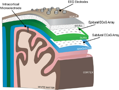
This project proposes a novel, implantable EEG sensing system. By leveraging neuromorphic principles and on-chip decoding, the proposed system greatly reduces power and bandwidth requirements. Fig 2. depicts the entire system, the electrodes are placed below the scalp but above the skull bone. The electrodes are interfaced with a neuromorphic spiking circuit, where the raw signals are converted to a spike train. The spike train is then classified by an on-chip spiking neural network (SNN), with the low-bandwidth outcome transmitted wirelessly. Fig 3. depicts the functional schematic of the on-sensor chip.
The spiking system bypasses the need for a power-intensive ADC and naturally interfaces with an on-chip SNN. The SNN decodes the spike train to classify epileptic state for continuous monitoring and only transmits the classification outcome across inductively coupled data links.
System Architecture

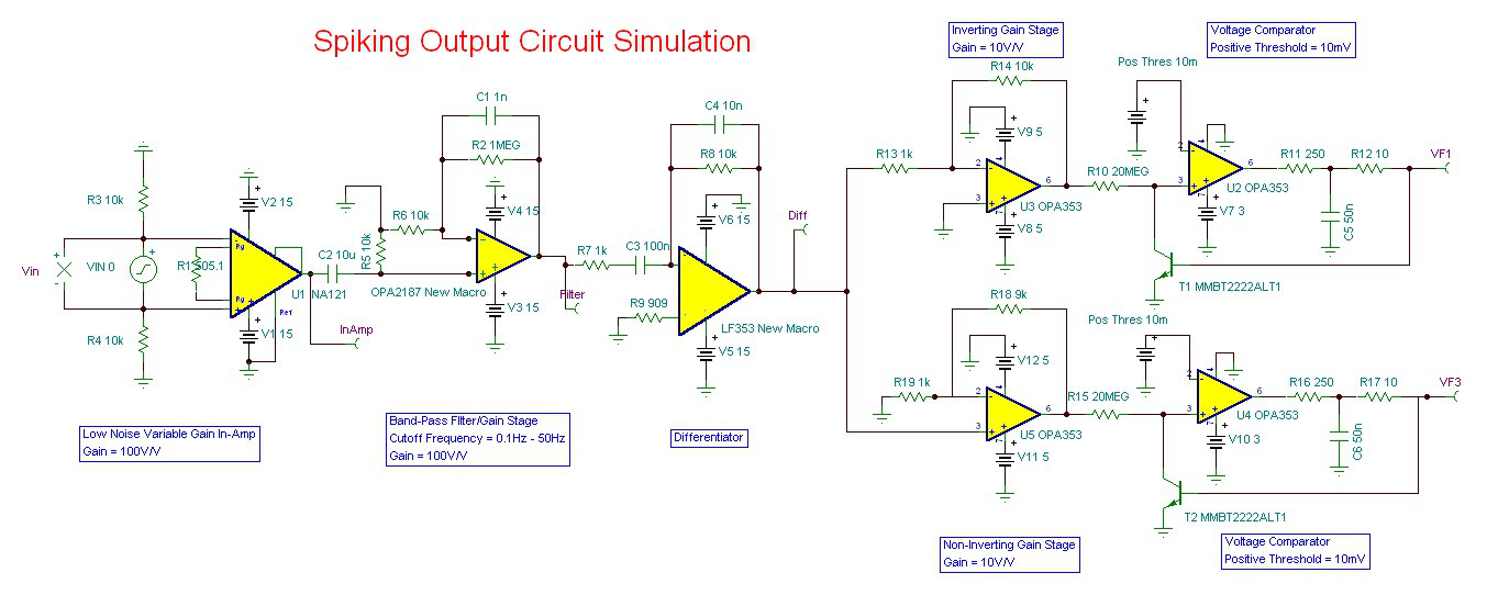
This section will focus largely on the on-sensor chip. Fig 4. describes the circuit-level simulations (proof-of-concept) for the spiking circuit. The sensed EEG signals are amplified by a low-noise amplifier circuit and then filtered by a cascade of two filters. The filtered signal is then passed into a spiking circuit. The spiking circuit passes the amplified signal through a first-order differentiator and compares the derivative to a set threshold. If the derivative exceeds the threshold, a positive/negative spike is generated.
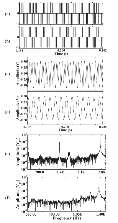
Specifically, spikes are generated if the rate of change in the input signal exceeds a positive or negative threshold - i.e. the spike rate corresponds to rate of change in input. Fig 5. highlights the PCB schematics of the test circuit and Fig 6. and Fig 7. illustrates the signal fidelity and reconstruction tests performed on the spike train output.
The spike train is then decoded by on-chip SNN to the detect/predict seizure onset.


My Contributions
- Performed literature review on neuro-scientific principles to inform design of neuromorphic circuit
- Designed the circuit prototype [incl. amplification, filtering, spiking circuit], first in SPICE using TINA, and then laid out a PCB test circuit, achieving estimated power consumption of 1mW
- Created software test bench to verify the spike generation circuit, including signal reconstruction, linearity of circuit, signal-to-noise error ratio
- Generated spiking dataset from raw EEG recordings of epileptic seizures for simulated training of on-chip spiking neural networks
Outcome
Currently in the process of preparing journal paper for submission.
